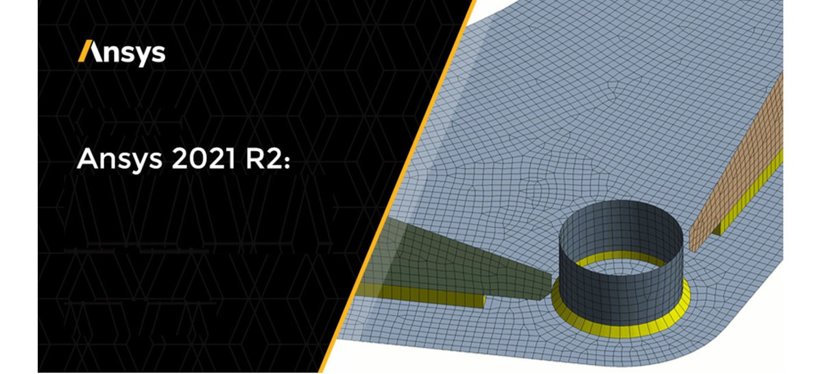
A line sketched in 2D becomes anĮdge when you pull your sketch into 3D. Show Edge 3D object composed of a single outside boundary of a feature. options control the display of connected and disconnected paths (i.e. OptionsĮdge when you pull your sketch into 3D. You can dock and detach these panels.Įdge 3D object composed of a single outside boundary of a feature. Show Contact settings in the Options Panel Sections of the user interface that initially appear along the left side of the application window and include: Structure panel, Layers panel, Selection panel, Groups panel, Options panel, and Properties panel. This allows you to get an isolated preview of the model’s face, edge, and vertex connections. to hide or show edge junctions, laminar edges, free beams, and beam junctions and ends. To further define your share topology, and to help you identify any failed or missing connections or parts, you can use the Edges and Vertices toggle check boxes in the Options panel Area of the user interface that enables you to modify functions specific to tools. Any shared topology displays on the model with blue lines.


 0 kommentar(er)
